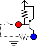
An inverter circuit. The red dot (on the left) marks the input signal from the joystick connector. The blue dot (on the right) denotes the switch contact on the USB game controller circuit.
Traditionally, game controllers on IBM compatible PCs have been of the analog type, while earlier gaming platforms, such as the 8-bit game consoles and home computers from the 1980s, have been equipped with digital joysticks. This has slowly been changing with the USB interface, which has introduced inexpensive digital game controllers for modern computers.
The inexpensive gamepad-type controllers often offer a poor
response, so that it is difficult to accurately control fast-paced
games with them. Where are good controllers like Suncom’s TAC-2? If your answer
is collecting dust in my closet
, read on.
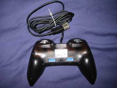
I got a Logitech WingMan Precision USB controller as a wedding present from a friend
with whom I have spent numerous Friday nights playing Dynablaster
several years ago. As my wife wasn’t too excited about this present,
I didn’t have to ask her permission before opening it. Besides, it
was not an expensive gift: such controllers can be bought for 5 to
20 €.
The controller I got has plenty of space inside for modifications, as it is based on a single IC that handles everything: the USB interface and the switches.
You will have to trace the signals on the circuit board of the USB game controller. It should not be too hard, as the device has probably been assembled on a single-sided circuit board, and the contact areas for the switches are fairly large. The largest area of copper are usually for the operating voltage. You can figure out the polarity by measuring the circuit board with a voltage meter while it is connected to an active USB interface. The interface provides a positive +5 V power supply.
After figuring out that most switches in the controller work by connecting signals to a common contact, it occurred to me that Atari VCS 2600 style joysticks work exactly in the same way.
If all switches share the ground contact, you are lucky: this common contact can be connected with the ground of the Atari joystick interfaces. If the common contact is not ground but +5 V, you can still proceed, but note that joysticks equipped with special features, such as autofire, may be damaged when plugged in.
On my Logitech WingMan Precision USB controller, the two trigger switches normally operated
by index fingers are not connected to the ground, but to the +5 V
supply. A simple PNP
transistor circuit is needed in order to convert the two signals from
the customary open-or-0 V
level to the
open-or-5 V
level expected by the controller.
The circuit is simple. Connect the signal line from the joystick connector to the base of a PNP transistor. Connect the base and the emitter of the transistor with a 1 kilo-ohm resistor. Connect the emitter to +5 V, and connect the collector to the input of the USB controller. One picture may be worth more than a thousand words:
An inverter circuit. The red dot (on the left) marks the input signal
from the joystick connector. The blue dot (on the right) denotes the
switch contact on the USB game controller circuit.
The modified Logitech WingMan Precision USB controller. The joystick
connectors are on the bottom side.
Using a Dremel tool, I drilled and milled two holes on the bottom side of the controller, for fitting two DE-9P connectors. These connectors were secured to the case with hot glue.
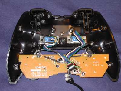
Added wirings inside the Logitech WingMan Precision USB controller.
Most signals are connected directly to the pins of the controller
chip.
It may be a good idea to use a ribbon cable instead of loose wires, so that the case can be mounted easily. It is best to only connect six wires to the DE-9P connectors, as follows:
Some joysticks need +5 V for special features, such as autofire. If you connect it, please be sure to limit the current with a resistor or a fuse in order to protect the USB interface of your computer.
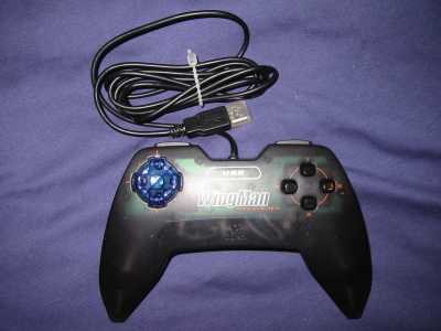
The modified Logitech WingMan Precision USB controller. The
installed ribbon cables are visible through the translucent case.
If you want to control two-player Commodore 64 games on VICE, you may be disappointed, because all buttons of the controller will be mapped to the fire button of the emulated joystick. Thus, only one joystick can be emulated with the controller, even though it had a sufficient number of inputs for connecting two joysticks.
I wrote the following simple patch to VICE, so that the emulation can be controlled with two joysticks connected to the single USB game controller. You may need to adapt the mapping to match your controller. Obviously, it would be better to program a user-configureable mapping.
--- vice-1.10/src/arch/unix/joy.c	2002-08-17 22:44:06.000000000 +0300
+++ vice-1.10/src/arch/unix/joy.c.new	2002-09-07 16:43:58.000000000 +0300
@@ -407,6 +407,15 @@
         close (ajoyfd[1]);
 }

+static void
+joy_set (int* joy, int mask, int set)
+{
+  if (set)
+    *joy |= mask;
+  else
+    *joy &= ~mask;
+}
+
 void new_joystick(void)
 {
     int i;
@@ -430,9 +439,14 @@
 	{
             switch (e.type & ~JS_EVENT_INIT) {
             case JS_EVENT_BUTTON:
-                joystick_value[i] &= ~16; // reset fire bit
-                if (e.value)
-		    joystick_value[i] |= 16;
+		switch (e.number) {
+		case 4: joy_set (&joystick_value[1], 16, e.value); break;
+		case 0: joy_set (&joystick_value[2], 2, e.value); break;
+		case 1: joy_set (&joystick_value[2], 8, e.value); break;
+		case 2: joy_set (&joystick_value[2], 4, e.value); break;
+		case 3: joy_set (&joystick_value[2], 1, e.value); break;
+		case 5: joy_set (&joystick_value[2], 16, e.value); break;
+		}
 		break;

 	    case JS_EVENT_AXIS:
A similar disappointment occurred with Atomic Bomberman
, the
sequel of Dynablaster
. It had a fixed mapping for the buttons,
and thus the mapping I had chosen for the fire button was useless.
You may want to install switches for selecting different fire button
mappings.
I thank Tomi Aropalo for donating the controller and Turo Heikkinen for helping me with the construction, especially for designing the inverter circuit and donating the transistors and resistors.